|
|
|
A vertical cut through the wing parallel to flight's direction (plan view) will show
trailing edge is called the Chord Line. The Chord Line cuts the airfoil into an upper surface and a lower surface. If we plot the points that lie halfway between the upper and lower surfaces, we obtain a curve called the Mean Camber Line. For a symmetric airfoil (upper surface the same shape as the lower surface) the Mean Camber Line will fall on top of the Chord Line. But for an asymmetric airfoil, these are two separate lines. The maximum distance between these two lines is called the Camber, which is a measure of the curvature of the airfoil (high camber means high curvature). Asymmetric airfoils are also known as cambered airfoils. The maximum distance between the upper and lower surfaces is called the Thickness. Both Thickness and Camber are expressed as a percentage of Chord. 
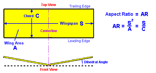
Airfoils can come with all kinds of combinations of camber and thickness distributions. They are designed for the condictions under which the plane is likely to be flown most of the time. NACA (the precursor of NASA) established a method of designating classes of airfoils and then wind tunnel tested the airfoils in order to provide lift coefficients and drag coefficients for designers. Aspect Ratio is a measure of how long and slender a wing is from tip to tip. The Aspect Ratio of a wing is defined to be the square of the span divided by the wing area and is given the symbol AR. The formula is simplified for a rectangular wing, as being the ratio of the span to the chord length as shown on the figure below. 
Wing Dihedral refers to the angle of wing panels as seen in the aircraft's front view. Dihedral is added to the wings for roll stability; a wing with some Dihedral will naturally return to its original position if it is subject to a briefly slight roll displacement. Most large airliner wings are designed with Dihedral. On the contrary the highly maneuverable fighter planes have no Dihedral. In fact, some fighter aircraft have the wing tips lower than the roots, giving the aircraft a high roll rate. A negative Dihedral angle is called Anhedral. << Previous Page |