|
|
|
|
By reducing the dimensions of a full-sized aircraft proportionally, a scaled model will be obtained, however, it seldom becomes an easy flying one. The main aerodynamic differences between a model and a full-sized aircraft are originated from the boundary layer, the thin layer of air close to the wing surface that is slowed down by skin friction. According to Osborne Reynolds, there are two main types of flow: The laminar and the turbulent. Which flow type occurs within the boundary layer at a given point of the wing's surface depends on the wing's form, the surface's roughness, the chord length, the airspeed and the ratio of density to viscosity of the air. Reynolds combined all those factors (except the surface condition) into a non- dimensional number known as Reynolds Number Re. Re = (air density/air viscosity) * air speed * wing chord Air viscosity is measured in kilograms per meter per second. The standard value is: 0.0000179 kg/m/sec. For instance, a wing with a chord of 1 meter at an airspeed of 1 m/sec and with the standard air density and viscosity will have the following Re: (1.225/0.0000179) * 1 * 1 = 68459 Thereby, a simplified formula may be obtained as follows: Re = 68459 * V * L Where V is the airspeed in m/sec and L the wing chord in meters. The Reynolds number is therefore dependent on the weather conditions, the wing chord and the airspeed. The Re increases as the airspeed, the air density and the wing chord increases. Since the wing chords of model aircraft are often much less than 1 meter, one may get a Re value close enough for modelling purposes by using the following simplified formula: Re = speed in kilometers per hour * chord in centimeters * 189 (Metric units). Re = speed in miles per hour * chord in inches * 770 (Imperial units). At low airspeed and small wing chord (as with a model aircraft) the air viscosity is a dominant factor, whereas with the full-sized aircraft the viscosity effects of the air are insignificant while the aircraft's mass inertia becomes more dominant. That's why one should not expect a scaled model aircraft to have the same flight characteristics as its larger counterpart. As stated in Forces in Flight, the lift force is dependent on the density of the air r, the airspeed V, the wing's Lift Coefficient and the wing's area according to the formula: Lift Force = 0.5 * r * V2 * Wing's Lift Coefficient * Wing's Area The Wing's Lift Coefficient is a dimensionless number that depends on the airfoil type, the wing's aspect ratio (AR), Reynolds Number (Re) and is proportional to the angle of attack (alpha) before reaching the stall angle. However, the wing's generation of lift also produces Induced Drag, which along with Parasitic Drag are forces that oppose the aircraft's motion through the air. One may also say that Induced Drag is the price we pay for getting lift. Induced Drag is also dependent on the density of the air r, the airspeed V, the wing's Drag Coefficient and the wing's area according to the formula: Drag Force = 0.5 * r * V2 * Wing's Drag Coefficient * Wing's Area The Wing's Drag Coefficient is a dimensionless number that depends on the airfoil type, the wing's aspect ratio (AR), the shape of the wing tips, Reynolds Number (Re) and the angle of attack (alpha). The relation between lift and drag is called the Lift to Drag ratio (L/D) and is obtained by dividing the Lift Coefficient by the Drag Coefficient. The characteristics of any particular airfoil may be represented by graphs showing the amount of lift and drag obtained at various angles of attack as well as the Lift/Drag ratio. The same airfoil has different Lift and Drag Coefficients at different Reynolds Numbers as shown in the graphs below: 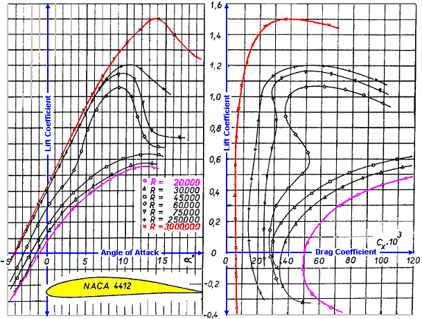
The above graphs refer to the airfoil only, as the Coefficients of a whole wing also depend on the wing's Aspect Ratio, Taper Ratio and on the shape of the wing tips. Note that this airfoil still produces lift at negative geometric angles of attack. The graphs also show a portion of the negative Coefficients (when flying inverted).
A large wing that is flying fast has a higher Re and thinner boundary layer than a small wing that is flying slow. The boundary layer is thinnest when its flow is laminar and thickens when it is turbulent. The turbulent flow may separate from the wing's surface, producing more drag and decreasing the lift, which may lead to stall. Thus, a low Re wing is more likely to suffer from laminar separation and to stall sooner than a wing with high Re.
The area of the flying surfaces (wings, fin and stabilizer) as well as the control surfaces (elevator, rudder and ailerons) should be proportionally larger in the model aircraft in order to obtain more controllable flights and landings. Wing loading is also more critical with smaller models. That means, a bigger model may have greater wing loading than a smaller one. Some basic rules of thumb may be followed when designing an easy flying trainer model according to the drawings below: 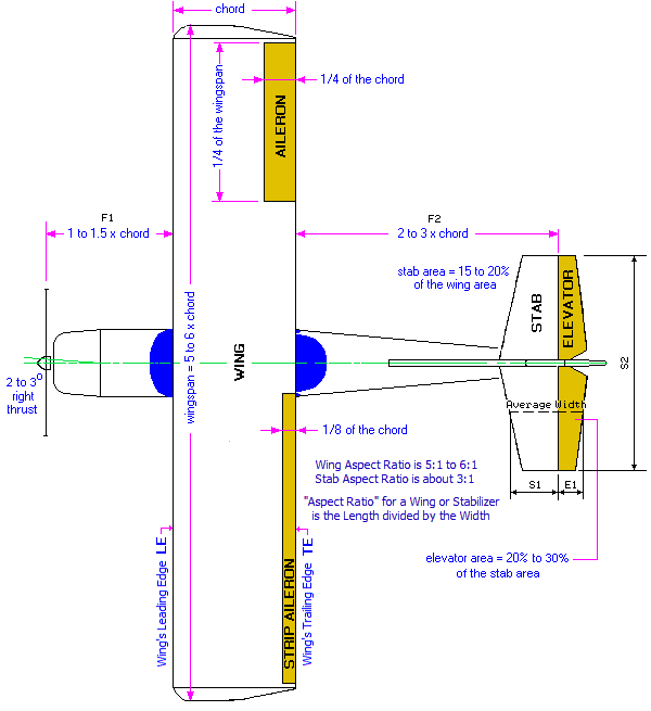
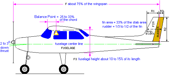
One may start by choosing the desired wingspan from which all other related dimensions may be calculated. With high wings the dihedral angle is typically between 3 to 6 degrees. Dihedral should be lower when using ailerons (up to 3 deg). Although not strictly needed, a wing washout angle between 3 to 5 degrees is advisable in order to improve stall characteristics. The ideal incidence and motor thrust angles are usually found by trial and error. Initially, one may start with 2 to 3 degrees down and right thrust. The wing's and stabilizer's incidence may preliminary be set at zero, and may be changed during test flights. Flat bottom wings may need more down thrust than symmetrical and/or semi- symmetrical ones. Landing gear placement on a tail dragger should have the axle coincident with the leading edge of the wing, whereas on a tricycle the main gear should be slightly aft of the Balance Point in order to get easier take-offs. A tail-heavy aircraft will be more unstable and susceptible to stall at low speed e. g. during the landing approach. A nose-heavy aircraft will be more difficult to takeoff from the ground and to gain altitude and will tend to drop its nose when the throttle is reduced. It also requires higher speed in order to land safely.
The performance of an engine powered model aircraft may also be estimated by calculating the weight / power ratio, also known as power loading. A slow and low wing loading (for a beginner), with a weight / power ratio of 440 to 500g/c.c. (270 to 300oz/c.in.) might be good enough, whereas an aerobatics would need about 340g/c.c. (200oz/c.in.) to achieve good performance. This is assuming 2-stroke engines and that the power of different types is pro- portional to their displacements, (which isn't too far off). For electric powered model aircraft, the input power for a trainer plane (no EDF), should be about 120 W/kg (55 W/lb) in order to get reasonable flying performance. Gliders and parkflyers may need much less power, 65 W/kg (30 W/lb), while the scale and aerobatics may need much more power, e.g. > 200 W/kg (90 W/lb). This assuming that the motor has about 75% efficiency. However, the power to weight ratio recommended above is by itself not enough to guarantee the aircraft's flight performance or whether it will fly at all, as other factors have to be taken into account, such as the pitch speed of the propeller, which refers to propeller's rpm times the pitch. The minimum pitch speed recommended is 2 to 3 times the plane's stall speed. The stall speed of an aircraft in mph (both model and full-scale) is approximately equal to four times the square root of the wing loading in ounces per square foot. To calculate the aircraft's approximate stall speed click here Another factor is the Static Thrust, which refers to how much the aircraft is pulled or pushed forward by the power system when the aircraft is stationary. The Static Thrust should be at least about 1/3 of the aircraft's weight. However, in order to be able to hover (3-D models), the Static Thrust should be greater than the aircraft's weight. To estimate the prop's approximate Static Thrust click here Note that the Static Thrust alone is not enough to predict how the aircraft will fly, as other factors like the prop pitch speed should also be considered. To check the Guidelines to help you choose your plane's Power System click here To estimate the suitable motor prop combo click here As for the airfoil type, one should consider that a flat bottom wing gives high lift at upright flight but poor lift at inverted flight. Flat bottom wings (high cambered airfoils) are mainly used in slow and relatively light powered models. They have high lift coefficient but also high pitching moment, so a relatively longer tail moment or larger stab area may be needed in order to achieve a good longitudinal stability (stability in pitch). They also tend to balloon when power is increased or when turning into the wind. Quasi-symmetrical airfoils are usually a good compromise giving almost the same lift at both upright and inverted flight. Symmetrical airfoils are intended for aerobatic models as it behaves equal at both upright and inverted flight. The control surfaces' max throws also have great effect on the flight stability. With a too much throw the model will respond too quickly and may be difficult to control, whereas too little throw will result in poor control, especially at low landing speed. Typical throw settings measured at the control surface trailing edge are: Elevator and Ailerons 6mm (1/4") up and down. Differential Ailerons (recommended with flat bottom wings) 8mm (5/16") up and 4mm (5/32") down. Rudder 10mm (3/8") left and right. Those figures are just guidelines and some minor changes may be done during test flights. Faster models will require lower throw settings. To increase the control surface throw, move the push rod to the hole on the control horn that is closer to the control surface and/or move the push rod to the further out hole on the servo arm. Some transmitters have dual rate facility, which allows the pilot to change the max throws to suit the flying speed. The picture below shows a typical radio installation. Both the battery and the receiver are wrapped up in soft foam to damp the engine's vibrations. 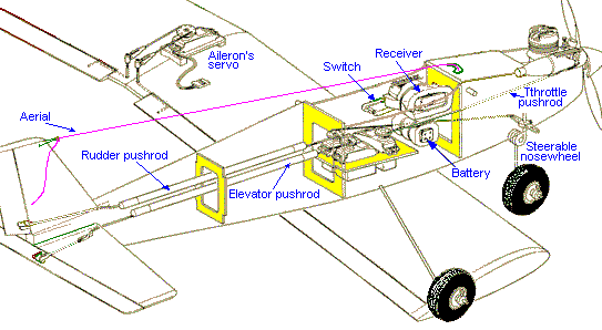
The material and construction methods depend on the model itself, personal preferences and on materials and tools available. Given enough power, almost anything can be made to fly - the question is how... One should also bear in mind that landing is an inevitable part of the flight. In order to avoid stall, a plane with high wing loading requires higher take-off and landing speed. Two planes with different sizes and with the same wing loading will have about the same stall speed, but the smaller one will seem to fly faster and will be more difficult to control, especially during landing approach. Thus, one should strive to build as light and as strong as possible. Typical wing loading of a 150cm wingspan (60 in) model plane is about 50g/sq.dm (16.4-oz/sq.ft). This value may be slightly higher with bigger models but should definitely be lower with smaller ones. The bigger planes allow for higher wing loadings compared to smaller ones. For instance, the wing loading of a full-scale Cessna 152 is about 510g/sq.dm (167-oz/sq.ft), a model aircraft with such a wing loading would hardly be able to fly. Wing loading is the aircraft's weight divided by the wing area. A reference that is not dependent on the aircraft size is the cubic wing loading, which is calculated dividing the weight by the wing area raised to the 1.5 power. For instance, the full scale Cessna has a cubic loading of about 13 oz/cu.ft, which puts it at the high end of a scale model category regardless of size. Different types of model aircraft may have different cubic wing loadings (oz/cu.ft) as shown below:
Beginners are advised to choose cubic wing loading values no greater than 8, as it's likely to give relatively low take-off and landing speeds. At higher cubic loadings one should expect increased landing and take-off speeds assuming no special lift devices are used, such as flaps. The area of a True Elliptical Wing = pi * 1/2 Span * 1/2 Chord 
The area of a Not True Elliptical = 0.5 * [(pi * 1/2 Span * Chord 1) + (pi * 1/2 Span * Chord 2)] 
As a rule of thumb the stall speed in mph is approximately equal to four times the square root of the wing loading in ounces per square foot. But if you know the whole wing's max lift coefficient, you may get a more accurate result with following formula: Stall speed (m/s) = [2*Weight / (Clmax*1.225*Wing Area)] 0.5 Where the weight is in Newton, area in m2 and standard air density 1.225kg/m3 Unless it's a glider, the prop's static pitch speed should be higher than 2.5 times the aircraft's stall speed. The static thrust should be at least about 1/3 of the planes' weight in order to get reasonable climb and acceleration capabilities after aborted landings. Some scaling rules: A scale model's weight should be reduced by the cube of the scale factor. For instance, a full-scale Piper J-3 Cub weights 1000lb and has 36ft wingspan. A 1/6 scale Piper J-3 Cub model should weight 1000/63 = 4.6lb. The wing loading of the scale model should be reduced by the scale factor's ratio. The 1/6 scale model should have 13.3 oz/sq.ft wing loading instead of 80 oz/sq.ft as the full-scale Piper J-3 Cub. Also to get a "scale-like" visual appearance in flight of scale models, one might reduce the speed of the full-scale aircraft by the scale factor's ratio in order to get a linearly scaled speed. For example, the full-scale J-3 Cub cruises at about 70 mph, thus a 1/2 size Cub should cruise at about 35 mph. To the eyes of the observer, both the model and full-scale should move the same number of fuselage-lengths per second, appearing to be flying at the same speed. However, this is not so easy to achieve, especially with smaller models outdoors. At 1/2 of the speed, the wing's lift (even ignoring Re effect) is only 1/16 as much. But, since the air molecules don't scale down when we reduce the plane's size, flying half as fast with half the size results in 1/4 Re, which further reduces the lift. Also the wind is not scaled down either, that means a 20 mph gust for a model is much more serious than 20 mph gust for the full-scale. So, flying at scale speed isn't so practical for small models, unless flying indoors. Some unit conversions: 1ft = 0.3048m 1in = 2.54cm 1lb = 16oz = 0.4536kg 1oz = 28.35g 1sq. ft = 144 sq. in Multiplying lb/sq.in by 2304 gives the value in oz/sq. ft. To download a complete Unit's Converter click on the picture below: 
Some interesting books: - for further details click on the pictures - 






Amazon Associates earn from qualifying purchases << Previous Page
|
| |||||||||||||||||||||||||||||||||||||||||||||||||||||||||||