--------------------

Amazon Associates earn
from qualifying purchases
|
|
|
Beginners' Guide
| First Model | Radio Control | Servos | Batteries | Pulsejet | Turbines | Electrics |
- Glow Engines
There are two main propulsion systems used by R/C models today:
The internal combustion systems (glow engines) and the electric motors.
Combustion engines' energy source has so far a higher energy/weight ratio
than the batteries used to power the electrics.
However, the combustion engines are usually more noisy and more prone to
oil spillage than the electric motors.
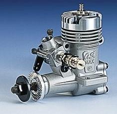
There are two types of glow engines:
The four-stroke and the two-stroke.
Two-stroke engines are the most used,
mainly because they are simple made,
light, easy to operate, easy to maintain,
and are usually inexpensive.
Two-stroke engines operate at a high
RPM and therefore can be quite noisy
without a good silencer.
|
|
Nevertheless, the four-stroke engines
also enjoy some popularity, mainly
because they produce a lower, more
scale-like sound and consume less fuel.
They have lower power/weight ratio and
lower RPM, but provide more torque
(use larger propellers) than theirs two-
stroke counter-parts.
|
|
However, since the four-stroke engines require high precision engineering and
more parts to manufacture, they are usually more expensive.
They also need more maintenance and adjustment than the two-stroke, yet they
are not too difficult to operate and maintain.
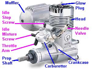
A glow engine consists basically of:
- Crankcase: which is the main body of the engine and houses the internal parts.
- Head: mounted on the top of crankcase. It has fins to provide engine cooling.
- Muffler: damps the exhaust noise as it exits the combustion chamber.
- Carburettor: to control the amount of fuel and air that enters the engine.
- Prop Shaft: is a part of the Crankshaft that protrudes from the crankcase.
- The Crankshaft transforms the movements of the Piston into rotational motion.
|
- The Piston has a cylindrical form and
operates by an up/down movement
(assuming the engine is viewed upright)
inside a sleeve, which is called Cylinder.
|
The glow motor's Carburettor consists basically of:
- Rotating barrel, which controls
the amount of fuel/air mixture
going to the combustion chamber.
- Throttle arm connected to the
barrel, which enables the engine's
speed to be controlled by a servo.
- Idle Stop Screw to adjust how
far the throttle barrel closes.
- Idle Mixture Screw to adjust the
amount of fuel entering the
carburettor while the engine
is idling.
- Needle Valve to adjust the
amount of fuel entering the
carburettor during medium and
high-speed operation.
|
|
All glow engines require a special fuel, called "glow fuel."
It consists of methanol as base, with some amount of nitromethane to increase
the energy and pre-mixed oil into the fuel, which lubricates and protects the
engine parts.
Two-stroke engines operate by igniting the fuel in its
combustion chamber once every turn of its crankshaft.
The fuel is mixed with air at the carburettor and forced
into the cylinder during the down movement of the
piston (1st stroke).
While the piston moves up, the mixture is compressed
and when the piston reaches the top, the glow plug
ignites the compressed gases, forcing the piston down
(2nd stroke).
On the way down exhaust gases escape through
the exhaust port while the fuel mixture enters the
cylinder again.
|
|
In a four-stroke engine the fuel/air mixture enters the combustion chamber during
the down movement of the piston through a valve operated by the camshaft
(1st stroke).
When the piston moves up, the valve closes and the mixture is compressed
(2nd stroke).
When the piston reaches the top, the glow plug ignites forcing the piston down
(3rd stroke).
On the next up movement of the piston, a second valve opens and allows the
exhaust gases to escape (4th stroke).
The piston moves down and the fuel mixture enters the combustion chamber
again, repeating the 1st stroke.
|
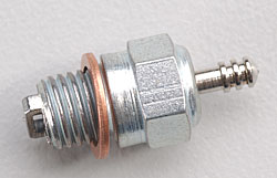
  The glow engines usually have a simple
  ignition system based on a glow plug
  made up of a little coil of platinum wire
  rather than a spark plug.
  A 1.5V battery is used to heat the glow
  plug only during the starting procedure
  and is removed when the motor reaches
  a certain rpm. This is possible because
  the glow plug keeps glowing by the heat
  produced during the compression and
  combustion without needing the battery.
|
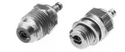
There are two lengths of glow plugs available.
The short ones are normally used on engines smaller than 2.5cc (.15cu in).
Some have a metal bar across the bottom of the plug called for Idle Bar, which
prevents raw fuel from dousing the heat from the element during idle.
There are also the so-called "hot" and "cold" glow plugs, which refer to their
effective coil operating temperature.
The glow plug's temperature depends on several factors, such as the coil's alloy,
thickness and length, the size of the hole in which the coil is located as well as
which material the glow plug's body is made of.
Usually smaller engines and those that run on less nitro prefer hotter plugs.
In case of doubt just follow the engine manufacturer's recommendation.
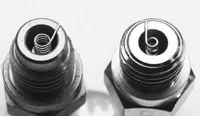
Turbo glow plugs have a chamfered end that matches the threaded hole on the
engine's head.
It is claimed to give less compression leakage around the glow plug and less
disruption of the combustion chamber.
Also the hole in the cylinder head, which exposes the glow plug to the air/fuel
mixture in the cylinder is much smaller, resulting in fewer rough edges that could
create unwanted hot spots.
The turbo plug is shown on the left of the picture below.
Glow engines may have plain bushed supported crankshaft or ball bearings.
Ball bearing engines usually have a better performance, run smoother, and last
longer but are more expensive than those with bushings.
The model engines' piston and cylinders construction are usually based in
two methods: Ringed engines or ABC.
Ringed engines have been the main method of construction until recently.
It consists of an aluminium or iron piston with a ring moving in an iron sleeve.
The ring provides the compression when operating.
Ringed engines are inexpensive to restore its compression after long usage by
simply replacing a ring, and are generally slightly cheaper.
They require an extended break-in period where the motor is run very rich to
provide lots of lubrication while the ring fits itself to the cylinder. They are also
more easily damaged if the engine is run too lean.
A more recent method is the ABC, which stands for Aluminium, Brass, Chrome
where an aluminium piston runs in a chrome plated brass sleeve.
The piston and cylinder are matched at the factory to give a perfect fit and good
compression.
ABC engines start easily by hand, give more power than the ringed engines,
have a good life-span and are less prone to damage with a lean run.
Schnuerle ported engines have several fuel inlet ports on three sides of the
cylinder allowing more fuel to flow to the combustion chamber.
This gives somewhat more power than with standard porting, which has only
one fuel inlet port on the side of the cylinder opposite the exhaust outlet.
A Schnuerle ported engine is usually slightly more expensive due to higher
manufacturing costs involved.
The fuel tank size and location affects the engine operation during the flight.
A typical tank placement is shown on the picture below:
When the engine is in the upright position, the fuel tank's centreline should
be at the same level as the needle valve or no lower than 1cm, (3/8in) to insure
proper fuel flow.
A too large fuel tank may cause the motor to run "lean" during a steep climb and
"rich" during a steep dive.
Normal tank size for engines between 3.5cc (.21) and 6.5cc (.40) is 150 - 250cc.
- Ducted Fans
In order to emulate the full-size aircraft jet-power systems, it is often used the
so-called Ducted Fan, there a glow-engine drives a fan fitted inside the model.
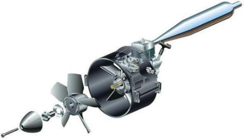
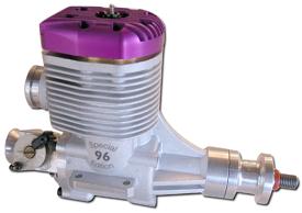
  There are also glow engines
  specially designed for Ducted
  Fans, which have a special
  shaped head, also having the
  exhaust port facing towards
  the rear of the model.
|
| 
|
These engines are often equipped with a tuned pipe exhaust in order to improve
their efficiency at high rpm.
Since a special method to start is often required due to the reduced access to
the engine, this arrangement is not recommended for beginners.
For further info and tips on how to extend the life of your engine check here

<< Previous Page
 Next Page >>
|
|