--------------------
Amazon Associates earn
from qualifying purchases
|
|
|
Beginners' Guide
| First Model | Radio Control | Batteries | Glow Engines | Pulsejet | Turbines | Electrics |
- Servos
Servos are the end units in a radio control chain.
They are used to move the aircraft's control surfaces, the motor throttle and
to actuate other devices such as retractable landing gears.
A servo consists basically in a motor, gearbox, feedback
potentiometer and an electronic board inside a plastic case.
Outside are the servo arm and the servo cable and plug.
The servo arm is often a plastic piece with holes on it
for attaching push rods or other mechanical linkages.
|
|
There are linear and rotary servos, but the most widespread today are the rotary
servos whose arm rotates about 45 degrees left and right from its centre point.
The picture on right shows some servo
hardware, such as mounting screws,
rubber pads, and different sorts of
servo arms.
|
|
The servo has an electronic circuit that compares the incoming control pulse
with a local generated one whose width corresponds to the servo arm's actual
position.
The servo's internal pulse width is determined by its feedback potentiometer
whose slider moves together with the servo's arm.
When the width of the incoming control pulse is different from the local generated,
the servo motor will rotate until the both pulses' width are equal.
The direction of rotation depends on whether the incoming pulse is wider or
shorter than the local pulse.
There are two operating concepts: the conventional servo and the digital servo.
The conventional servo circuit uses a pulse stretcher to widen the pulse difference
between the incoming pulse and the locally generated.
Thereby a 1% pulse difference produces a 50% duty cycle for motor drive.
A continuous drive signal will be obtained when the pulse difference is over 10%.
Also a small dead band is provided to prevent the servo being in continuous state
of motion when insignificant pulse differences occur.
The difference between the conventional and the digital servo is that the pulse
drive to the motor occurs every 20mS with the conventional, whereas with the
digital occurs (for example) every 3.3mS, which means that the digital servo
sends pulses to the motor at a much higher frequency.
Digital servo incorporates a microprocessor, which receives the input pulse
signal and generates power pulses to the servomotor based on preset values.
Some brands offer the possibility to program certain parameters such as
Dead-Band Width, Direction of Rotation, Neutral Point, Servo Arm Throw and
End Point.
The digital servo is supposed to have constant torque throughout the servo travel,
faster control response and more accurate positioning, but at the expense of
greater power consumption.
Servos are available in different shapes, sizes, weights and output torque.
Typically they may be sorted as follows:
Giant - weights around 100gr (3.5oz)
Standard - 45gr (1.6oz)
Mini - 20gr (.70oz)
Micro - 8gr (.28oz)
Pico - 5.5gr (.18oz)
Wes Technik - 2.1gr (.08oz)
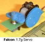
Falcon Servo - 1.7 gr
|
Some of the smallest servos on the market today:
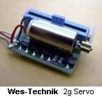
|
Further lighter systems use a coil/magnet concept, and may weight less
than 1gr (.035oz). However, they need a special tailored receiver.
A more detailed description about the coil/magnet system may be found here.

<< Previous Page
 Next Page >>
|
|